
Power Electronics - Section 1 (2)
Power Electronics - Section 1
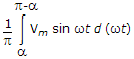
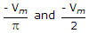
| 9. | In a single phase full wave converter (M-2 connection) feeding on R - L load, the input voltage is v = Vm sin ωt. The expression for dc output voltage is |
|||||||
Answer: Option C Explanation: Due to inductive load the period of conduction is a to p + a in each half cycle. |


| 10. | The number of leads in an SCR are : |
|||||||
Answer: Option B Explanation: Anode, cathode and gate. |
| 11. |
|
|||||||
Answer: Option A Explanation: |


| 12. | Thyristors are not suitable for logic circuits. |
|||
Answer: Option B Explanation: Thyristors can be used for logic circuits. |
| 13. | In a thyristor the gate current is increased, then |
|||||||
Answer: Option C Explanation: Gate current does not affect the magnitude of anode current. |
| 14. | Assertion (A): A transistor requires a continuous base signal for conduction but a thyristor requires a gate pulse. Reason (R): Transistor find widespread application in power electronic circuits. |
|||||||
Answer: Option C Explanation: Transistors are used but not very widely. |
| 15. | A single phase half wave controlled rectifier circuit has a free wheeling diode. The load is a combination of R and L. The firing angle is a. The period of conduction of SCR and free wheeling diode respectively are |
|||||||
Answer: Option A Explanation: SCR conducts from a to p and free wheeling diode from p to (2p + a). |
| 16. | Assertion (A): The surge current which an SCR can withstand is much higher than rms on state current. Reason (R): The duration of surge current is very small. |
|||||||
Answer: Option A Explanation: Since duration of surge current is small, the associated energy is small. |