
Memory and Storage - General Questions (7)
Memory and Storage - General Questions
| 49. |
|
|||||||
Answer: Option C Explanation: No answer description available for this question. Let us discuss. |
| 50. |
|
|||||||
Answer: Option C Explanation: No answer description available for this question. Let us discuss. |
| 51. | Refer the given figure. The outputs (Q0–Q3) of the memory are always LOW. The address lines (A0–A7) are checked with a logic probe and all are indicating pulse activity, except for A3, which shows a constant HIGH, and A7, which shows a constant LOW; the select lines,
|
|||||||
Answer: Option A Explanation: No answer description available for this question. Let us discuss. |
 are checked and
  shows pulse activity, while
  indicates a constant HIGH. What is wrong, and how can the memory be tested to determine whether it is defective or if the external circuitry is defective?
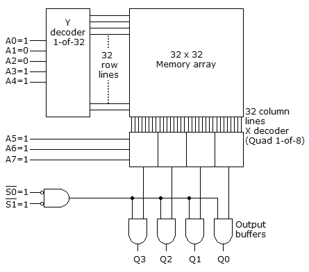
| 52. |
|
|||||||
Answer: Option D Explanation: No answer description available for this question. Let us discuss. |
| 53. |
|
|||
Answer: Option B Explanation: No answer description available for this question. Let us discuss. |
| 54. |
|
|||||||
Answer: Option B Explanation: No answer description available for this question. Let us discuss. |
| 55. |
|
|||||||
Answer: Option D Explanation: No answer description available for this question. Let us discuss. |
| 56. |
|
|||||||
Answer: Option D Explanation: No answer description available for this question. Let us discuss. |