Flip-Flops - General Questions
Flip-Flops - General Questions
| 1. |
|
|||||||
Answer: Option C Explanation: No answer description available for this question |
| 2. |
|
|||||||
Answer: Option A Explanation: No answer description available for this question |
| 3. |
|
|||||||
Answer: Option A Explanation: No answer description available for this question |


| 4. |
|
|||||||
Answer: Option D Explanation: No answer description available for this question |
| 5. |
|
|||||||
Answer: Option A Explanation: No answer description available for this question. |
| 6. | A 555 timer is connected for astable operation as shown below along with the output waveform. It is determined that the duty cycle should be 0.5. What steps need to be taken to correct the duty cycle, while maintaining the same output frequency? |
|||||||
Answer: Option D Explanation: No answer description available for this question |

| 7. |
|
|||||||
Answer: Option B Explanation: No answer description available for this question. |
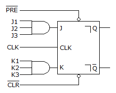
| 8. | The circuit given below fails to function; the inputs are checked with a logic probe and the following indications are obtained: CLK, J1, J2, J3, K1, K2, and K3 are pulsing. Q and
|
|||||||
Answer: Option C Explanation: No answer description available for this question. |
 are HIGH.
  and PRE are LOW. What could be causing the problem?