Counters - General Questions (5)
Counters - General Questions
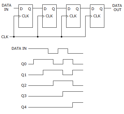
| 33. | How many data bits can be stored in the register shown below?
|
|||||||
Answer: Option A Explanation: No answer description available for this question |
| 34. |
|
|||||||
Answer: Option B Explanation: No answer description available for this question. |
| 35. |
|
|||||||
Answer: Option D Explanation: No answer description available for this question |
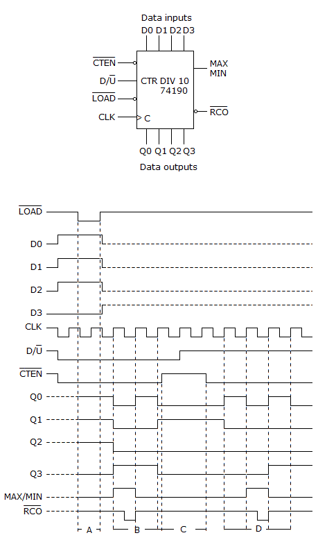
| 36. | What function will the counter shown below be performing during period "B" on the timing diagram?
|
|||||||
Answer: Option A Explanation: No answer description available for this question |
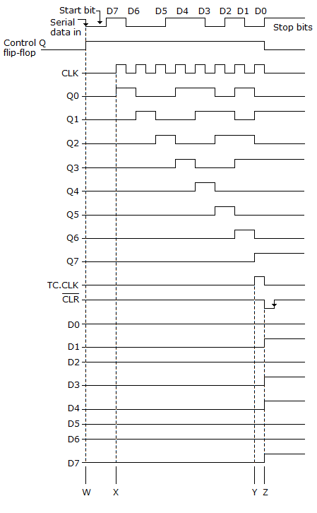
| 37. | Referring to the given figure, what causes the Control FF to reset after D7?
|
|||||||
Answer: Option C Explanation: No answer description available for this question. |
| 38. |
|
|||||||
Answer: Option A Explanation: No answer description available for this question. |
| 39. |
|
|||||||
Answer: Option C Explanation: No answer description available for this question |
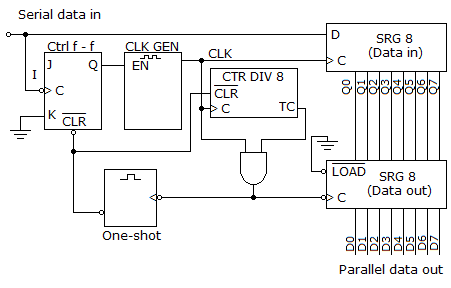
| 40. | What function does the CTR DIV 8 circuit given below perform?
|
|||||||
Answer: Option D Explanation: No answer description available for this question. |