IndiaBIX
IndiaBIX
Start typing & press "Enter" or "ESC" to close
  • Home
  • Jobs
  • Results
  • Current Affairs
  • GK
  • Online Test
  • HR Interview
  • BLOG

Automatic Control Systems - Section 1 (4)

  • Home
  • Electronics & Communication Engineering
  • Electronics and Communication Engineering
  • Automatic Control Systems - Section 1
Directions to Solve

Automatic Control Systems - Section 1

25. 

Consider the systems with following open loop transfer functions

1.23-203-1

2.23-203-2

3.23-203-3

If unity feedback is used, the increasing order of time taken for unit step response to settle is

A. 1, 2, 3
B. 3, 1, 2
C. 2, 3, 1
D. 3, 2, 1

Answer: Option C

Explanation:

42-203 For the three systems the values of ξωn are 1.8, 2.5 and 2 respectively.

Hence values of T are 0.55, 0.4 and 0.5 respectively.

View Answer Discuss Workspace Report

26. 

Assertion (A): The steady state response, of a stable, linear, time invariant system, to sinusoidal input depends on initial conditions.

Reason (R): Frequency response, in steady state, is obtained by replacing s in the transfer function by jω

A. Both A and R are correct and R is correct explanation of A
B. Both A and R are correct but R is not correct explanation of A
C. A is correct but R is wrong
D. R is correct but A is wrong

Answer: Option D

Explanation:

Steady state response does not depend on initial conditions.

View Answer Discuss Workspace Report

27. 

Bellows converts

A. pressure difference into displacement
B. pressure difference into voltage
C. displacement into pressure difference
D. either (a) or (c)

Answer: Option A

Explanation:

To measure pressure, it is convenient to convert pressure into displacement and then use a displacement transducer.
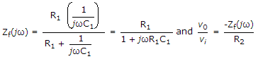
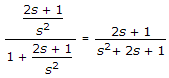
View Answer Discuss Workspace Report

28. 

A unity feedback system has open loop transfer function 14-57 The closed loop transfer function is
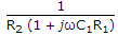
A. 14-57-1
B. 14-57-2
C. 14-57-3
D. 14-57-4

Answer: Option B

Explanation:

41-57

View Answer Discuss Workspace Report

29. 

In the given figure, of potentiometer V0 = Vi (R0/Ri) only when

31-316

A. RL = 0
B. RL = ∞
C. RL is neither low nor high
D. RL is low but not zero

Answer: Option B

Explanation:

If RL is not infinite, the voltage ratio of potentiometer depends on the value of RL. This is called loading effect.
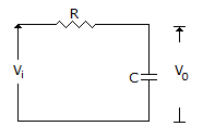
View Answer Discuss Workspace Report

30. 

In the given figure the input frequency is such that R << Xc, then

32-346

A. v0 lags vi by 90°
B. v0 leads vi by 90°
C. v0 and vi are in phase
D. either (b) or (c)

Answer: Option A

Explanation:

Voltage across capacitor lags by 90°.

View Answer Discuss Workspace Report

31. 

A system has its two poles on the negative real axis and one pair of poles lies on jω axis. The system is

A. stable
B. unstable
C. limitedly stable
D. either (a) or (c)

Answer: Option C

Explanation:

Poles on j x-axis lead to oscillations.

View Answer Discuss Workspace Report

32. 

For the circuit in the given figure,20-167-11

20-167

A. 21-167-1
B. 21-167-2
C. 21-167-3
D. 21-167-4

Answer: Option C

Explanation:

42-167

View Answer Discuss Workspace Report

  • 1
  • 2
  • 3
  • 4
  • 5
  • 6
  • 7

Questions & Answers

Aptitude Chemical Engineering Civil Engineering Computer Science & Engineering Current Affairs Data Interpretation Electrical & Electronics Engineering Electronics & Communication Engineering General Knowledge Logical Reasoning Mechanical Engineering Non Verbal Reasoning Verbal Ability Verbal Reasoning

Interviews

HR Interview

Jobs

Sarkari Jobs

Results

Rojgar ResultSarkari Result

Admission

Admission 2023

Admit Card

Admit Card 2023

Answer Key

Answer Key 2023
copyright
Privacy Policy
© 2025 IndiaBIX. All Rights Reserved.

Report