Microwave Communication - Section 1 (2)
- Home
- Electronics & Communication Engineering
- Electronics and Communication Engineering
- Microwave Communication - Section 1
Microwave Communication - Section 1
| 9. |
|
|||
Answer: Option A Explanation: It uses a single cavity resonator for generating microwave oscillations. Its parts are electron gun, resonator, repeller and output coupling. It operates on the principle of positive feed back. The repeller electrode is at negative potential and sends the partially bunched electron beam back to resonator cavity. This positive feedback supports oscillations. Its feature are: 1. Frequency range - 2 to 100 GHz 2. Power output - 10 MW to about 2 W 3. Efficiency - 10 - 20 % Its applications include radar receivers, local oscillator in microwave devices, oscillator for microwave measurements in laboratories etc. |
| 10. | Assertion (A): A coaxial line is a non-radiating line. Reason (R): In a coaxial line the electric and magnetic fields are confined to the region between the concentric conductors. |
|||||||
Answer: Option A Explanation: Since the fields are confined, there is no radiation. |
| 11. |
|
|||||||
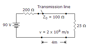
Answer: Option D Explanation: Because rv = 1 at each end, the line voltage will not reach a steady value and oscillations will continue indefinitely. |
| 12. |
|
|||
Answer: Option A Explanation: It is somewhat similar to TWT and can deliver microwave power over a wide frequency band. It has an electron gun and a helix structure. However the interaction between electron beam and RF wave is different than in TWT. The growing RF wave travels in opposite direction to the electron beam. The frequency of wave can be changed by changing the voltage which controls the beam velocity. Moreover the amplitude of oscillations can be decreased continuously to zero by changing the beam current. It features are: 1. Frequency range - 1 GHz to 1000 GHz. 2. Power output - 10 mV to 150 mW (continuous wave) 250kW (pulsed). It is used as signal source in transmitters and instruments. |
| 13. | Assertion (A): Artificial transmission lines are frequently used in laboratories. Reason (R): An artificial transmission line can be used to represent an actual line and can also be used as a delay circuit, as attenuator, as filter network etc. |
|||||||
Answer: Option A Explanation: Artificial transmission lines have many applications. One of the applications is to simulate an actual line in the laboratory. |
| 14. |
|
|||||||
Answer: Option C Explanation:
|
| 15. |
|
|||||||
Answer: Option C Explanation: It is somewhat similar to TWT and can deliver microwave power over a wide frequency band. It has an electron gun and a helix structure. However the interaction between electron beam and RF wave is different than in TWT. The growing RF wave travels in opposite direction to the electron beam. The frequency of wave can be changed by changing the voltage which controls the beam velocity. Moreover the amplitude of oscillations can be decreased continuously to zero by changing the beam current. It features are: 1. Frequency range - 1 GHz to 1000 GHz. 2. Power output - 10 mV to 150 mW (continuous wave) 250kW (pulsed). It is used as signal source in transmitters and instruments. |
| 16. |
|
|||||||
Answer: Option D Explanation: The condition for minimum distortion is found by equating |


 The result is