
Voltage Regulators - General Questions (2)
Voltage Regulators - General Questions
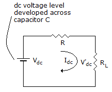
| 9. | This circuit is an example of the ac equivalent of an RC filter.
|
|||
Answer: Option B Explanation: No answer description available for this question.
|
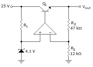
| 10. | Refer to the given figure. If the BE junction of Q1 opens, the output voltage VOUT will
|
|||||
Answer: Option B Explanation: No answer description available for this question. |
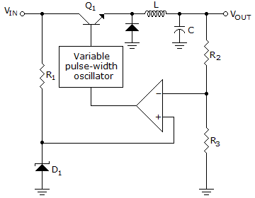
| 11. | Refer to the given figure. The inductor and capacitor are used for
|
|||||||
Answer: Option D Explanation: No answer description available for this question.
|
| 12. |
|
|||||||
Answer: Option A Explanation: No answer description available for this question.
|
| 13. |
|
|||||||
Answer: Option B Explanation: No answer description available for this question.
|
| 14. |
|
|||||||
Answer: Option C Explanation: No answer description available for this question.
|
| 15. |
|
|||||
Answer: Option B Explanation: No answer description available for this question.
|
| 16. |
|
|||||||
Answer: Option C Explanation: No answer description available for this question.
|