
Analog Electronics - Section 1 (6)
Analog Electronics - Section 1
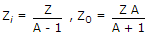
| 41. | Gain of the amplifier is 'A'. Then the I/P impedance and O/P impedance of the closed loop amplifier shown below would be |
|||||||
|


| 42. | The load impedance ZL of a CE amplifier has R and L in series. The phase difference between output and input will be |
|||||||
Answer: Option D Explanation: It is 180° for purely resistive load and between 180° and 270° for R-L load. |
| 43. | In figure v1 = 8 V and v2 = 4 V. Which diode will conduct? |
|||||||
Answer: Option B Explanation: D1 will conduct and the output voltage will be about 7 V. Therefore D2 will be reverse biased and will not conduct. |

| 44. | and 10 VAn RC coupled amplifier has an open loop gain of 200 and a lower cutoff frequency of 50 Hz. If negative feedback with β = 0.1 is used, the lower cut off frequency will be |
|||||||
|

| 45. | A half wave diode circuit using ideal diode has an input voltage 20 sin ωt volts. Then average and rms values of output voltage are |
|||||||
|
 and 10 V
 and 10 V
 and VC = 0.5 x 20 = 10 V.
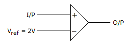
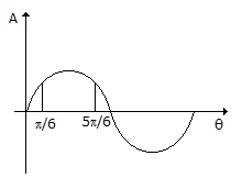
| 46. | If the input to the ideal comparator shown in the figure is a sinusoidal signal of 8 V (peak to peak) without any DC component, then the output of the comparator has a duty cycle of |
|||||||
|

| 47. | Which of the following oscillators is suitable for frequencies in the range of mega hertz? |
|||||||
Answer: Option C Explanation: Only LC oscillators are suitable for MHz range. |
| 48. | For a base current of 10 μA, what is the value of collector current in common emitter if βdc = 100 |
|||||||
Answer: Option C Explanation: IC = 10 x 100 μA = 1 mA. |