IndiaBIX
IndiaBIX
Start typing & press "Enter" or "ESC" to close
  • Home
  • Jobs
  • Results
  • Current Affairs
  • GK
  • Online Test
  • HR Interview
  • BLOG

Automatic Control Systems - Section 1

  • Home
  • Electronics & Communication Engineering
  • Electronics and Communication Engineering
  • Automatic Control Systems - Section 1
Directions to Solve

Automatic Control Systems - Section 1

1. 

For the system of the given figure the transfer function is

27-245

A. 27-245-1
B. 27-245-2
C. 27-245-3
D. 27-245-4

Answer: Option D

Explanation:

Transfer function = 43-245

View Answer Discuss Workspace Report

2. 

In a minimum phase system

A. all poles lie in the left half plane
B. all zeros lie in the left half plane
C. all poles lie in the right half plane
D. all except one pole or zero lie in the left half plane

Answer: Option B

Explanation:

For stability poles must be in left half plane. Zeros in left half plane lead to minimum phase shift.
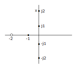
View Answer Discuss Workspace Report

3. 

For very low frequencies, v0/vi in the given figure equals

32-346

A. 1
B. 0
C. ∞
D. 0.5

Answer: Option A

Explanation:

For low frequencies Xc is very high as compared to R. Hence  44-346

View Answer Discuss Workspace Report

4. 

The given figure shows a pole zero diagram. The transfer function G(j1) is

21-174

A. 0.5 ∠0
B. 2.7 ∠- 31°
C. 2 ∠45°
D. 2 ∠- 67.4°

Answer: Option A

Explanation:

Join j1 point with the zero and poles. Find magnitude and phase angles of all these lines.
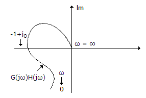
View Answer Discuss Workspace Report

5. 

The system in the given figure, has

36-395

A. good gain and phase margin
B. poor gain and phase margin
C. good gain margin but poor phase margin
D. poor gain margin but good phase margin

Answer: Option D

Explanation:

Since the plot is very near (-1 + j0) point, gain margin is poor.
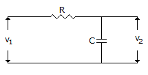
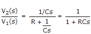
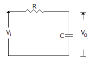
View Answer Discuss Workspace Report

6. 

For the circuit in the given figure, V2(s)/V1(s) =

27-258

A. 27-258-1
B. 27-258-2
C. 27-258-3
D. 27-258-4

Answer: Option B

Explanation:

43-258

View Answer Discuss Workspace Report

7. 

In the given figure, if R = XC, voltage gain is

32-346

A. 0 dB
B. 3 dB
C. -3 dB
D. 20 dB

Answer: Option C

Explanation:

If R = XC, V0 = 0.5 Vi Hence gain is -3 dB.

View Answer Discuss Workspace Report

8. 

For the system in the given figure,

25-225u

A. 25-225-1
B. 25-225-2
C. 25-225-3
D. none of the above

Answer: Option B

Explanation:

For inner loop we have transfer function = 43-225

43-225-1=43-225-2

View Answer Discuss Workspace Report

  • 1
  • 2
  • 3
  • 4
  • 5
  • 6
  • 7

Questions & Answers

Aptitude Chemical Engineering Civil Engineering Computer Science & Engineering Current Affairs Data Interpretation Electrical & Electronics Engineering Electronics & Communication Engineering General Knowledge Logical Reasoning Mechanical Engineering Non Verbal Reasoning Verbal Ability Verbal Reasoning

Interviews

HR Interview

Jobs

Sarkari Jobs

Results

Rojgar ResultSarkari Result

Admission

Admission 2023

Admit Card

Admit Card 2023

Answer Key

Answer Key 2023
copyright
Privacy Policy
© 2025 IndiaBIX. All Rights Reserved.

Report